

Views: 0 Author: Site Editor Publish Time: 2026-10-08 Origin: Site


Picture a busy Tuesday morning. Drivers pull up, swipe payment cards, select fuel grades, and fill their tanks. Millions interact with these machines daily. They remain largely oblivious to the highly regulated, precision-engineered machinery humming just inches away. However, behind that sleek metal panel lies a complex ecosystem. Hydraulics, electronics, and safety valves work in perfect synchronization.
Whether you own a gas station looking to optimize uptime or a maintenance technician troubleshooting a fault, visualizing the system through a comprehensive parts diagram proves incredibly valuable. For facility managers and equipment buyers, knowing the exact technical functions of these components marks the first step toward making informed maintenance decisions. Planning to upgrade a heavy-duty commercial fuel dispenser requires understanding both internal and external anatomy. This knowledge ensures operational safety and dramatically simplifies future troubleshooting procedures.
Operating a commercial fueling station demands strict adherence to environmental regulations and fire safety protocols. Consequently, studying a fuel pump components layout provides immense practical value for various stakeholders.
From an engineering perspective, having a clear mental map of the system allows for much faster diagnostics. Imagine a scenario where a pump dispenses at a frustratingly slow trickle. Instead of blindly swapping out parts, a technician who understands the system architecture bypasses guesswork entirely. They systematically isolate the issue. They determine whether the fault lies in a clogged 10-micron filter, a failing hydraulic circuit, or a malfunctioning electronic pulser. This precision reduces repair times and minimizes the risk of accidental fuel exposure.
Furthermore, understanding this layout leads to superior inventory management for station owners. Identifying which components are prone to wear allows operators to stock essential spare parts in advance. This proactive approach prevents extended equipment downtime, keeps customers happy, and ensures continuous compliance with strict local safety regulations.
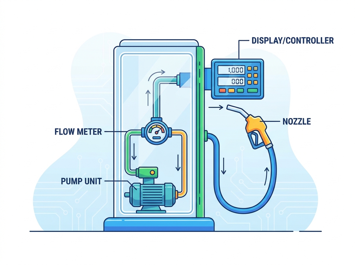
The sleek exterior of a modern gas pump hides a sophisticated network of hydraulic paths. Breaking down the internal layout reveals exactly how raw fuel safely transfers from an underground storage tank to a vehicle with pinpoint accuracy.
The method used to draw fuel depends entirely on the pumping system installed. In a suction pump setup, the explosion-proof motor and pumping unit reside directly inside the dispenser housing. The motor drives a rotary vane pump or gear pump that creates a vacuum. This action pulls the liquid upward through the piping. High-quality industrial fuel dispenser units typically feature motors designed for continuous operation under harsh conditions. Conversely, a submersible turbine pump system places the motor directly inside the underground tank. This submersible unit pushes pressurized liquid up to the dispenser. Submersible systems dominate large commercial stations since a single underground pump can supply pressurized fuel to multiple dispensers simultaneously.
Engineers often consider the flow meter the mechanical heart of the accuracy system. It measures the exact volume of liquid passing through the piping. As fuel flows through this chamber, it forces internal precision pistons or gears to rotate. The internal volume of these chambers is precisely calibrated. Therefore, each movement corresponds to a specific volume of fuel. Leading equipment achieves a remarkable accuracy rate of plus or minus 0.2 percent. This mechanical data then converts into electronic pulses via a pulser device, ensuring accurate billing.
Once the fuel is measured, its flow rate requires strict control. The solenoid valve acts as the primary gatekeeper of the hydraulic circuit. When a customer pre-pays for a specific amount, the dual-stage solenoid valve opens fully. This allows a fast flow rate initially, often reaching 50 to 80 liters per minute for standard vehicles. As the dispensed amount nears the target price, the electronic controller signals the valve to restrict the flow to a slow trickle. Finally, it shuts off the fuel instantly to prevent over-dispensing. In the event of a power failure, this valve defaults to a closed position.
If the flow meter acts as the heart, the electronic controller serves as the brain. This microprocessor board receives pulse data from the flow meter. It calculates the total price based on current rates and communicates directly with the station point-of-sale system. It also controls the digital display screens. To operate safely in hazardous zones, manufacturers house these processing boards in rugged, explosion-proof enclosures.
While internal mechanics handle measurement, external components are engineered for user convenience and immediate physical safety. These are the parts consumers handle directly on the forecourt.
The dispensing nozzle serves as the primary point of physical interaction. It features a highly sensitive automatic shut-off mechanism based on the Venturi effect. When fuel reaches the tip of the nozzle, it blocks a small air hole. This creates a sudden change in pressure that mechanically triggers the nozzle to snap shut, preventing dangerous overflows.
Equally critical is the breakaway valve located on the upper section of the hose. Drive-offs remain a common hazard at busy stations. This safety device snaps apart under specific tension. It instantly seals both ends of the fuel line to prevent catastrophic spills on the concrete.
Industrial fuel hoses must meet rigorous durability requirements. Manufacturers construct them with layers of synthetic rubber and braided steel wire. This withstands chemical degradation from petroleum products, UV exposure, and the physical crush of vehicle tires. To enhance ergonomics, a multi-plane swivel joint connects the hose to the nozzle. This allows the nozzle to rotate freely without twisting or stressing the main hose.
The modern transaction interface has evolved significantly to combat fraud. Today dispensers feature secure card readers that protect consumers from skimming devices. The keypad allows for secure PIN entry. Meanwhile, the high-contrast LED display screens provide clear visibility of pricing and volume. These screens remain sealed tightly against dust and moisture ingress.
Taking a static diagram and putting it into motion reveals a highly synchronized process. When a customer pulls up to refuel, a coordinated dance of electronic authorization and hydraulic movement begins.
First, the point-of-sale system verifies the payment and sends an electronic authorization signal to the dispenser microprocessor. The system resets the display screens to zero. As the customer lifts the nozzle from the boot, a switch signals the controller to activate the pump motor and commands the solenoid valve to open.
Once the user squeezes the nozzle handle, pressurized fuel travels from the underground tank. It passes through the filters and into the flow meter. The internal gears turn, sending continuous electrical pulses to the motherboard. As fuel exits the nozzle, an integrated vapor recovery system captures displaced gasoline fumes and routes them back underground.
Finally, when the tank is full, the nozzle Venturi mechanism triggers an automatic mechanical shut-off. The controller signals the solenoid valve to close electronically, and the pump motor deactivates.
The evolution of fueling technology is stark when comparing older mechanical pumps to contemporary digital kiosks. Recent industry trend analysis reveals a massive shift toward interconnected, data-driven forecourts. Market data indicates that commercial operators are moving away from reactive repairs. Instead, they heavily favor IoT-enabled predictive maintenance and modular designs.
By utilizing smart sensors, modern stations can detect a pressure drop in a filter long before it impacts the customer experience. Furthermore, the global push for alternative fuels is driving the demand for modular dispensers. Modern stations require equipment capable of handling various fuel blends alongside traditional diesel and gasoline. This shift underscores the importance of investing in a highly adaptable high-performance fuel dispenser that can seamlessly integrate with future cloud-based management systems.
To better understand the value of modern upgrades, examining the technical differences is crucial for station owners.
| Feature | Traditional Mechanical Dispensers | Modern Smart Dispensers |
|---|---|---|
| Data Processing | Mechanical gear-driven counters | Microprocessor with real-time POS integration |
| Maintenance | Reactive repair after component failure | IoT predictive diagnostics and error codes |
| Flow Rate Control | Single-stage mechanical valves | Proportional dual-stage solenoid valves |
| User Interface | Basic segmented LCD or rolling dials | High-contrast multimedia LED screens |
| Security | Basic padlock access | EMV-compliant payment and encrypted pulser data |
Even the most robustly engineered equipment undergoes degradation through continuous daily use. By referencing your equipment schematic, you can implement proactive facility maintenance.
Filters: Located internally just before the flow meter, fuel filters serve as the first line of defense against particulate matter. They typically utilize a 10-micron rating for gasoline and 30-micron for diesel. As they trap debris, they gradually clog. This restricts hydraulic pressure and results in slow pumping speeds.
Nozzle Spouts and Scuff Guards: Because nozzles frequently drop on concrete forecourts, the aluminum spouts become bent. This compromises the vacuum seal required for the automatic shut-off. The rubber scuff guards also degrade and require replacement to prevent scratching vehicles.
Fuel Hoses: Despite their reinforced construction, hoses remain vulnerable to extreme temperature fluctuations. Operators must routinely inspect them for surface cracking or exposed wire braiding to prevent high-pressure ruptures.
O-Rings and Seals: Throughout the hydraulic circuit, small rubber O-rings maintain pressurized seals. Over time, exposure to harsh chemical additives causes them to dry out. Weeping leaks often trace back to degraded O-rings. Technicians should swap these out using chemically resistant materials like Viton.
When a component inevitably fails or when planning a station upgrade, sourcing the correct equipment is critical. The primary decision buyers face involves matching technical specifications to actual site demands.
First, evaluate the required flow rate. Standard retail stations typically need dispensers outputting 50 liters per minute. However, truck stops and heavy-duty commercial sites require high-flow models capable of 80 to 120 liters per minute to service large diesel tanks efficiently.
Second, prioritize Original Equipment Manufacturer parts. OEM parts are engineered to exact specifications and rigorously tested. While aftermarket parts present a lower initial cost, they often lack stringent quality control. Using non-compliant components alters flow dynamics and potentially voids warranties.
Third, verify regulatory certifications. Fuel dispensers operate in highly explosive environments. Therefore, the entire unit and its replacement parts must carry appropriate safety listings. Look for OIML approvals for measurement accuracy and ATEX or UL certifications for explosion-proof safety. Ensuring your smart gas station equipment meets these standards guarantees long-term operational integrity.
A commercial fuel dispenser is far more than a simple pump. It represents a highly engineered system where mechanical hydraulics, electronic sensors, and stringent safety valves work in perfect harmony. From the precise measurements of the flow meter to the life-saving snap of a breakaway valve, every piece plays a vital role.
Keeping a detailed parts diagram handy stands as a fundamental best practice for any station operator. It empowers you to perform proactive maintenance, identify wear parts early, and prevent costly operational downtime.
If your station experiences frequent breakdowns or you are ready to modernize your forecourt, do not wait for a complete system failure. For reliable, high-accuracy, and explosion-proof fueling solutions, explore the advanced product lineup at Bei-lin. Contact their certified equipment specialists today to source high-quality replacement parts or upgrade your fueling infrastructure with industry-leading technology.
To locate the exact schematic for your equipment, check the manufacturer operation manual. You can also find the metal identification plate riveted to the exterior housing. This plate contains the exact model and serial numbers required to look up the correct diagram online.
The breakaway valve on the hose and the shear valve located at the base of the pump are paramount. The shear valve is designed to sever and instantly shut off the main fuel supply line from the underground tank if a vehicle crashes into the dispenser.
The automatic shut-off is controlled by a mechanical Venturi tube inside the nozzle. As fuel fills the vehicle tank and covers the tip of the nozzle, it blocks a small sensing port. This blockage causes a rapid change in air pressure, which mechanically releases the hold-open latch and snaps the valve shut.
Industry standards dictate that fuel dispenser filters should be replaced every 300,000 liters of fuel dispensed, or at least twice a year. However, if you notice a sudden drop in dispensing speed, the filter is likely clogged with tank sediment and requires immediate replacement.
A pulser error typically occurs when the electronic controller stops receiving signals from the flow meter. This can be caused by a damaged communication cable, moisture ingress in the pulser housing, or mechanical binding within the flow meter gears. A certified technician must inspect the internal wiring and sensor alignment.


