

Views: 0 Author: Site Editor Publish Time: 2026-07-12 Origin: Site


In modern fueling infrastructure, every dispensed drop translates directly into revenue. A precisely engineered solenoid valve for gas station applications acts as the heart of this transaction. It ensures exact metering while upholding stringent safety protocols in hazardous environments. Replacing or upgrading these dispenser valves is never just a routine maintenance task. Instead, it represents a critical compliance and revenue-protection decision for station operators. Even milliseconds of delayed closure can lead to significant financial loss over time.
This article provides procurement specialists and maintenance engineers with a clear, objective framework. You will learn how to evaluate various valve types, understand crucial sizing metrics, and navigate manufacturer requirements confidently. We eliminate the marketing fluff. Instead, we focus purely on technical performance, safety compliance, and operational reliability.
Precision equals revenue: Valve response times directly dictate dispensing accuracy, preventing costly product giveaway on pre-paid transactions.
Flow control variations matter: A dual flow control valve is mandatory for retail accuracy, whereas a standard solenoid valve suffices for basic bulk transfer.
Specs drive safety: Thread sizing (e.g., a standard 3/4 solenoid valve) must pair perfectly with explosion-proof (EX) certified coils and fuel-compatible diaphragm seals.
OEM vs. Aftermarket: Specifying an OEM solenoid valve ensures native integration with dispenser electronics, mitigating warranty and compliance risks.
Fuel dispenser performance relies heavily on rapid flow interruption. When a customer prepays for a specific fuel volume, the system must shut off instantly upon reaching that target. Any hesitation causes immediate financial leakage.
Delayed valve closures result directly in over-dispensing. A sluggish diaphragm might stay open just 500 milliseconds too long. In high-flow scenarios, this delay pushes extra ounces of fuel into the customer's tank. You do not bill for this extra volume. We call this phenomenon "product giveaway." Multiply a few lost ounces by hundreds of daily transactions across multiple dispensers. The monthly financial impact quickly spirals into thousands of dollars in lost revenue. Precision directly protects your profit margins.
Fuel environments demand absolute adherence to global safety standards. Regulators classify gas stations as hazardous zones due to constant vapor presence. Dispenser valves must carry specific certifications like ATEX, UL, or IECEx. These ratings verify the component can operate safely amid explosive gases. The electrical coil housing must contain any potential internal spark. Ignoring these non-negotiable compliance standards exposes operators to catastrophic safety failures and severe legal liabilities.
Retail fuel environments are notoriously harsh. Dispensers operate continuously under extreme duty cycles. Internal components experience violent temperature swings, from freezing winter mornings to scorching summer afternoons. These conditions stress valve bodies, internal seals, and electromagnetic coils. Continuous operation requires robust materials. You must select components designed specifically for high-frequency cycling to avoid unexpected station downtime.
Understanding the mechanical differences between valve types helps you specify the correct unit for your application. Engineers primarily choose between two distinct architectures.
A standard solenoid valve relies on a simple binary mechanism. It operates in only two states: fully open or fully closed. When energized, the coil lifts the plunger, allowing maximum fuel flow. When de-energized, it snaps shut instantly. This immediate action makes single-stage units excellent for commercial fleet fueling or bulk transfer operations. You generally deploy them where exact monetary metering to the penny remains unnecessary. They offer durability and simplicity but lack the nuanced control required for modern retail prepay scenarios.
Retail gas stations face a different challenge. Customers expect the pump to stop exactly on a pre-set dollar amount. A dual flow control valve solves this problem. It features a primary high-flow stage and a secondary low-flow stage. We often call this secondary stage the "trickle" setting.
This architecture provides a significant bottom-of-funnel advantage. As the dispensed amount approaches the prepay target, the primary stage closes. The dispenser then slows the fuel rate to a trickle using the secondary stage. Once it hits the exact target, the secondary valve closes abruptly. This staged shutdown provides two massive benefits. First, it enables exact monetary metering. Second, it prevents hydraulic shock, commonly known as water hammer. Sudden fluid stops can rupture pipes or damage sensitive metering equipment. The two-stage design eliminates this destructive kinetic energy transfer.
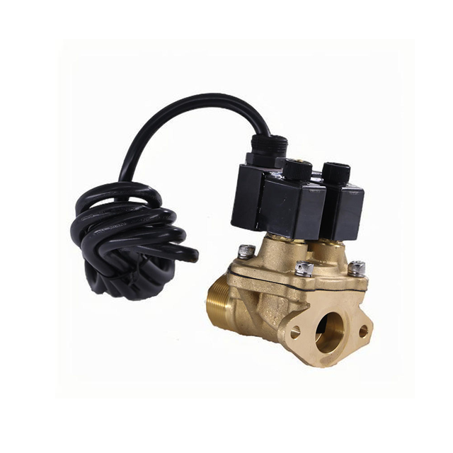
Selecting the correct valve requires matching physical and electrical specifications to your dispenser’s exact needs. Procurement teams must evaluate several technical criteria before making a final decision.
Internal pipe diameters dictate fuel velocity. You must evaluate your standard dispenser requirements carefully. A 3/4 solenoid valve remains the undisputed industry standard for retail dispensers. This size comfortably handles standard retail flow rates, which typically range between 40 and 50 liters per minute. However, commercial truck stops operating high-flow diesel pumps require significantly larger ports. You will typically specify 1-inch or 1.5-inch ports to accommodate flow rates exceeding 100 liters per minute without causing severe pressure drops.
Modern fuels are highly aggressive chemical cocktails. Ethanol blends (E10, E85) and Biodiesel readily degrade inferior materials. You must assess both the rigid body material and the flexible internal seals.
The following chart illustrates typical fluid compatibility for gas station environments:
Fuel Type | Recommended Body Material | Recommended Seal Material | Materials to Avoid |
|---|---|---|---|
Standard Unleaded | Brass, Aluminum | Nitrile (Buna-N), Viton (FKM) | Natural Rubber |
Ethanol Blends (E85) | Stainless Steel, Treated Aluminum | Teflon (PTFE), Specialized Viton | Standard Nitrile, Untreated Brass |
Biodiesel Blends | Stainless Steel | Teflon (PTFE) | Nitrile, EPDM |
Choosing the wrong elastomer leads to premature diaphragm swelling, cracking, and eventual failure.
Your valve coil must match the dispenser controller's electrical output perfectly. Common control boards supply 220V AC, 110V AC, or 24V DC. Connecting a 110V coil to a 220V circuit results in immediate catastrophic failure. Furthermore, you must verify the explosion-proof housing ratings. The enclosure must effectively isolate any electrical arcs from the surrounding fuel vapors, maintaining strict ATEX or UL compliance.
System pressure dictates valve operation. Engineers must evaluate Minimum and Maximum Operating Pressure Differentials (MOPD). Pilot-operated valves require a minimum pressure differential to lift the diaphragm off its seat. If the line pressure drops too low, the valve simply will not open fully. Conversely, if the pump pushes line pressure beyond the MOPD, the electromagnetic coil lacks the strength to open against the fluid force. Proper pressure matching ensures the unit opens reliably and seals tightly.
The procurement debate often centers on original equipment versus third-party replacements. Both paths carry distinct implications for safety, warranty preservation, and system longevity.
Specifying a genuine OEM solenoid valve guarantees native integration. Dispenser manufacturers like Gilbarco, Tatsuno, Wayne, and Tokheim design proprietary electronic controllers. These motherboards expect specific electrical resistance and current draw from the valve coils. Original parts match these parameters flawlessly. Furthermore, sticking with OEM parts preserves existing equipment warranties. It also maintains the original safety certifications issued for the dispenser assembly as a complete unit.
Third-party replacements often tempt buyers with lower initial price tags. However, you must carefully calculate the associated risks. A slight mismatch in coil resistance can draw excessive current. This overdraw frequently burns out Triac switches on expensive dispenser motherboards. Additionally, varying spring tensions in aftermarket diaphragms affect closing response times, throwing off meter calibration.
You should generally reserve aftermarket alternatives for legacy equipment. When original OEM parts become obsolete, third-party solutions keep older pumps running. If you take this route, ensure the aftermarket part carries identical third-party safety certifications (UL/ATEX). Never install uncertified electrical components in a hazardous zone.
Even the highest-quality components eventually succumb to physical wear. Understanding common failure modes helps maintenance teams implement effective preventative strategies.
Valves typically fail via electrical faults or mechanical obstructions.
Coil Burnout: This occurs frequently due to facility voltage fluctuations. Prolonged activation times also generate excessive heat, melting internal coil windings.
Mechanical Obstruction: Debris poses a massive threat. Rust flakes, dirt, or pipe sealant can bypass inadequate filters. When debris lodges under the diaphragm, it prevents perfect seating. The valve then leaks continuously, causing pump calibration errors.
Elastomer Degradation: Chemical attack from harsh fuel additives hardens flexible seals, eventually causing them to crack and rupture.
Proper installation practices drastically extend component lifespans. Follow these structured steps during deployment:
Install Upstream Filtration: Always place high-quality strainers (typically 80 to 100 mesh) immediately upstream of the valve body. This catches rust and debris before it ruins the diaphragm seat.
Flush the Lines: Purge new pipework thoroughly to remove manufacturing shavings or excess thread sealant before installing the control unit.
Secure Wiring Terminations: Ensure all electrical connections inside the explosion-proof junction box remain tight and sealed. Moisture ingress causes rapid short circuits.
When evaluating different models, closely examine their serviceability. Good designs allow maintenance technicians to rebuild internal components without breaking pipe joints. You should be able to replace a burnt coil or a torn diaphragm inline. Removing the entire heavy brass body from the pipework takes hours. Inline serviceability reduces dispenser downtime from hours to mere minutes, significantly improving station profitability.
Selecting the appropriate flow control mechanism remains a vital operational decision. You must balance precise metering requirements with aggressive fuel compatibility and strict regulatory compliance. Standard binary valves handle bulk transfers efficiently, while proportional two-stage units are absolutely mandatory for accurate retail prepay transactions. Always prioritize equipment that matches your dispenser's exact electrical and pressure parameters.
For your next steps, we recommend buyers audit their current dispenser control boards immediately. Verify your exact flow rate requirements and pipe diameters. Before finalizing any purchase orders, request exact technical drawings and current ATEX or UL certificates from potential suppliers. Rigorous vetting protects your revenue, preserves your equipment warranties, and ensures absolute safety on the forecourt.
A: Over-dispensing usually points to a failing secondary coil in a dual flow control valve. If the low-flow stage cannot close instantly, fuel continues to trickle out. Alternatively, a torn internal diaphragm or debris trapped under the seal prevents immediate and complete fluid shutoff.
A: No. Retail dispensers require a dual-stage valve to slow the fuel flow just before final shutoff. A standard single-stage unit stops fuel too abruptly. This sudden stop causes hydraulic shock, damages equipment, and fails to hit exact prepay monetary targets accurately.
A: Only if they are equipped with specialized internal seals. Standard nitrile (Buna-N) seals degrade quickly when exposed to high ethanol concentrations. You must specify corrosion-resistant internal components and chemical-grade elastomers like specific grades of Viton or PTFE for E85.
A: Replacement schedules depend on cycle counts and fuel cleanliness rather than strict timeframes. Preventative maintenance usually involves inspecting upstream filters regularly. Most operators plan to replace diaphragms every 3 to 5 years, or immediately if any response lag or minor leakage is detected.


